Compiler Basics
Compilers was one of my favorite classes in school alongside OS and architecture. It gave me a deeper understanding of what happened with my code behind the scenes and insight into how to create my own domain specific language. Knowing how compilers work create the link between the abstractions that developers use everyday and the machine executing them below.
Phases
Compilation comes into five phases.
- Scanner - Breaks up text into tokens.
- Parser - Arranges the tokens into relationships that form a tree.
- Symbol Table - Attributes metadata like type and scope to identifiers (e.g. variables, functions, classes).
- Intermediate Representation (IR) - Representation of the code that is typically a series of statements / commands that can be optimized before becoming the assembly code.
- Compiled Code - The actual assembly code that gets generated at the end as a series of opcodes with their corresponding data and control bits.
Of course this description makes a lot of assumptions and doesn’t account for different approaches to compilation but serves well for the purpose of learning and demonstration. For the following phase breakdowns we will use a C like language with a simple set of constructs as a toy use case. Let’s get started…
Scanner
This is also known as the lexer or tokenizer. It’s responsibility is to take text and create indivisible units / tokens out of it. For example, the following…
int x = 123;
…would be tokenized as int, x, =, 123, and ;.
Let’s take a more complex example.
void foo(int& bar) {
  bar = 123;
}
This would be tokenized as int, foo, (, int, &, bar, ), {, bar, =, 123, ;, and }.
As a contrast, let’s look at a Python like snippet…
def foo(bar):
  bar = 123
Since these languages treat spaces as part of the language (unlike C-like ones), this would be tokenized as def, foo, (, bar, ), :, \n, \s, \s, bar, =, and 123. This approach is a bit nuanced though as any spaces after : and before newline are not tokenized since they have no meaning for the compiled language (same goes for extraneous newlines). This is why the last C-like example could be expressed as.
void foo(int&bar){bar=123;}
The only case where spaces have any meaning is to separate identifiers.
Now let’s take an example we will use going forward for all the phases.
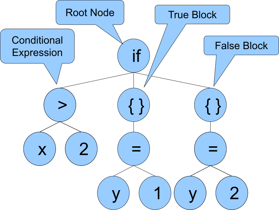
if (x > 2) {
  y = 1;
} else {
  y = 2;
}
Parser
The parser phase transforms the tokens into relationships between them (semantical) where it takes the flat list of tokens and puts them into a tree structure (i.e. Abstract Syntax Tree (AST)). Here is what our example looks like.
Something useful to know is the difference between the scanner and parser phase.
- The scanner phase is the lexical component, it is concerned with the structure of symbols / tokens (in this case a combination of letters, numbers and punctuation).
- The parser phase is the semantic component, it is concerned with the meaning of symbols as they relate in the context of one another. For example…
void foo() { int x = (1+1) + 1; }
The parenthesis are the symbols present in the function declaration and the function body but they have completely different meaning in their relationship with the rest of the symbols.
- One is in the context of a function declaration
fooand denotes the start and end of declared parameters. - The other imposes order of operation on the expression assigned to the variable
x.
This is what makes the parsing / semantic phase different than the scanner / lexical phase.
Symbol Table
The symbol table provides information about the identifiers such as type and scope. Let’s take the canonical example we have been using and encapsulate it into a function so we can give it some scope.
void foo(int x) {
  int y;
  if (x > 2) {
    y = 1;
  } else {
    y = 2;
  }
}
The code gets stored in the symbol table as…
| Symbol | Type | Scope |
|---|---|---|
| foo | function, void | global |
| x | int | function parameter |
| y | int | block scope |
A symbol table is defined and typically stored in each compilation unit that corresponds to an object file (e.g. *.o, *.obj). These tables are not only used for metadata but will also serve as lookups for other object files that are trying to resolve their own symbols in the linker phase.
Slight Detour to Undefined Reference
Note this is around the phase where you will get errors like undefined reference. The linker in these cases is trying to link the symbol references between the object files. An example of an undefined reference.
// This says, I promise this thing exists. Just keep compiling and
// it will show up when the linker searches for it.
extern int foo();

int bar() {
  int x = foo();
  return x + 2;
}
The symbol table will be generated as…
| Symbol | Type | Scope |
|---|---|---|
| foo | function, void | extern (note this) |
| bar | function, int | global |
| x | int | block scope |
If foo isn’t included anywhere either directly or indirectly through headers, an undefined reference will get reported. In these cases, the linker couldn’t resolve the symbol scope, which has an extern placemarker waiting for linkage.
Back on Track
Let’s now assume the extern int foo(); is defined in another file. The resolved symbol table becomes.
| Symbol | Type | Scope |
|---|---|---|
| foo | function, void | int (note this has changed) |
| bar | function, int | global |
| x | int | block scope |
Intermediate Representation (IR)
Generated from the parser graph and symbol table is the intermediate code / representation. It is the code that gets generated before translating to assembly. The reason this exists as opposed to direct assembly translation is so that optimizations can be made before final code expression.
IR generators come in different types and take on different degrees of responsibility. Examples of IRs are LLVM, Java bytecode, and Microsoft CIL.
.NET CIL
Applying the .NET Common Intermediate Language (CIL) to our canonical example below…
void foo(int x) {
  int y;
  if (x > 2) {
    y = 1;
  } else {
    y = 2;
  }
}
…becomes…
.method private hidebysig instance void
          foo(int32 x) cil managed
{
  .maxstack  2
  .locals init (int32 V_0, bool V_1)
  IL_0000:  nop
  IL_0001:  ldarg.1
  IL_0002:  ldc.i4.2
  IL_0003:  cgt
  IL_0005:  ldc.i4.0
  IL_0006:  ceq
  IL_0008:  stloc.1
  IL_0009:  ldloc.1
  IL_000a:  brtrue.s   IL_0012

  IL_000c:  nop
  IL_000d:  ldc.i4.1
  IL_000e:  stloc.0
  IL_000f:  nop
  IL_0010:  br.s       IL_0016

  IL_0012:  nop
  IL_0013:  ldc.i4.2
  IL_0014:  stloc.0
  IL_0015:  nop
  IL_0016:  ret
}
This is an instance of a stack based bytecode representation as opposed to a register based approach. The two approaches are not strictly one or the other, but typically a virtual machine uses one predominantly. The more popular JVM and CIL are stack based but sometimes leverage registers. For example, the CIL will store simple constants like integers or perform calculations using registers since it is faster in terms of memory access than the L1+ cache.
Compiled Code
The last and final step is the machine code itself. This is usually the assembly code that gets ran. Using our previous example for the CIL code. This bytecode gets translated into x86 code as…
C.foo(Int32)
  L0000: push ebp
  L0001: mov ebp, esp
  L0003: sub esp, 0x10
  L0006: xor eax, eax
  L0008: mov [ebp-0xc], eax
  L000b: mov [ebp-0x10], eax
  L000e: mov [ebp-4], ecx
  L0011: mov [ebp-8], edx
  L0014: cmp dword ptr [0x1adec1a8], 0
  L001b: je short L0022
  L001d: call 0x661dfc10
  L0022: nop
  L0023: cmp dword ptr [ebp-8], 2
  L0027: setg al
  L002a: movzx eax, al
  L002d: mov [ebp-0x10], eax
  L0030: cmp dword ptr [ebp-0x10], 0
  L0034: je short L0042
  L0036: nop
  L0037: mov dword ptr [ebp-0xc], 1
  L003e: nop
  L003f: nop
  L0040: jmp short L004b
  L0042: nop
  L0043: mov dword ptr [ebp-0xc], 2
  L004a: nop
  L004b: nop
  L004c: mov esp, ebp
  L004e: pop ebp
  L004f: ret
Into the Abyss
Let’s go even further now and see what the encoded values look like in the instruction register of an x86 CPU. On the left are the line numbers and the contents of the register, and on the right is the assembly equivalent. Notice how some of the hex matches value to the right.
0:  55                      push   ebp
1:  89 e5                   mov    ebp,esp
3:  83 ec 10                sub    esp,0x10
6:  31 c0                   xor    eax,eax
8:  89 45 f4                mov    DWORD PTR [ebp-0xc],eax
b:  89 45 f0                mov    DWORD PTR [ebp-0x10],eax
e:  89 4d fc                mov    DWORD PTR [ebp-0x4],ecx
11: 89 55 f8                mov    DWORD PTR [ebp-0x8],edx
14: 83 3d a8 c1 de 1a 00    cmp    DWORD PTR ds:0x1adec1a8,0x0
1b: 74 05                   je     22 <L0022>
1d: e8 0c fc 1d 66          call   661dfc2e <L004f+0x661dfbdf>
22: 90                      nop
23: 83 7d f8 02             cmp    DWORD PTR [ebp-0x8],0x2
27: 0f 9f c0                setg   al
2a: 0f b6 c0                movzx  eax,al
2d: 89 45 f0                mov    DWORD PTR [ebp-0x10],eax
30: 83 7d f0 00             cmp    DWORD PTR [ebp-0x10],0x0
34: 74 0c                   je     42 <L0042>
36: 90                      nop
37: c7 45 f4 01 00 00 00    mov    DWORD PTR [ebp-0xc],0x1
3e: 90                      nop
3f: 90                      nop
40: eb 09                   jmp    4b <L004b>
42: 90                      nop
43: c7 45 f4 02 00 00 00    mov    DWORD PTR [ebp-0xc],0x2
4a: 90                      nop
4b: 90                      nop
4c: 89 ec                   mov    esp,ebp
4e: 5d                      pop    ebp
4f: c3                      ret
The byte layout from left to right is opcode, control bits, data. Imagine being the person that had to execute all of this manually.
This was considered a step up from this.

Because they didn’t want to do this.
01010101
1000100111100101
100000111110110000010000
11000111000000
100010010100010111110100
100010010100010111110000
100010010100110111111100
100010010101010111111000
10000011001111011010100011000001110111100001101000000000
111010000000101
1110100000001100111111000001110101100110
10010000
10000011011111011111100000000010
11111001111111000000
11111011011011000000
100010010100010111110000
10000011011111011111000000000000
111010000001100
10010000
11000111010001011111010000000001000000000000000000000000
10010000
10010000
1110101100001001
10010000
11000111010001011111010000000010000000000000000000000000
10010000
10010000
1000100111101100
01011101
11000011
In fact the whole concept of an assembler was once considered by some as a wasteful endevour. It was using computational resources to create instructions to use computational resources. The whole point is that it used computational resources! In today’s world where we are pretty wasteful of computational resources by orders of magnitude, this was not taken for granted back then when the idea of computational time sharing was a thing. We have come a long way.
Closing Thoughts
So now we have come full circle from…
void foo(int x) {
  int y;
  if (x > 2) {
    y = 1;
  } else {
    y = 2;
  }
}
…to the binary seen above.
The compiler is a great thing, it allows us to use abstractions that make development much easier and express ideas in ways that humans are more able to grasp. Turning the realm of controlled electrons into that of the symbolic and philosophical, permitting us to process and interpret the world around us.
References & More Reading
- To start exploring on how to create a language for yourself, check out Antlr (lexer) and Bison (parser).
- My First Language Frontend with LLVM Tutorial - Exactly what it says.
- Lecture notes on Writing a Toy Compiler.
- ASTs - What they are and how to use them - Engaging blog post on how ASTs work and dives further into other topics also covered here.
- GodBolt: Compiler Explorer - Fantastic online IDE to view compiled assembly from high level languages.
- Let’s make a Teeny Tiny compiler, part 1 - First part of a series showing how to make a compiler using Python. Trivial but approachable and demonstrative to learning compilers.
Leave a comment